Texture and Color
Stages of Rendering
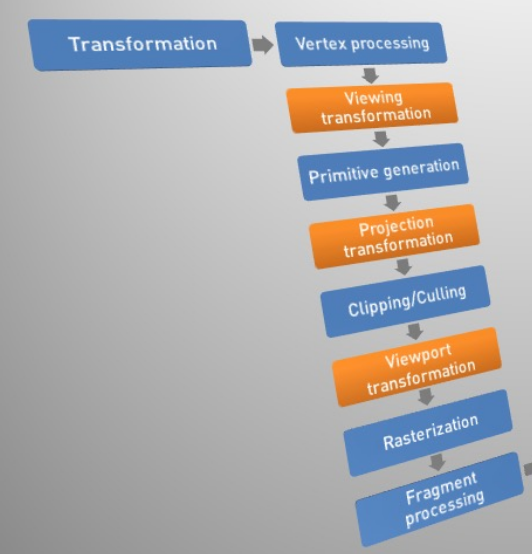
The vertex processing calculates the lighting on each vertex (emissive + ambient + diffuse + specular = output vertex colour). Furthermore, this step includes the vertex shader.
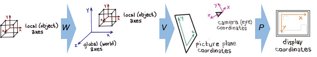
After this step, viewing transformation transforms the world coordinates into the camera space.
Then, the primitive generation step assembles the primitives and if there is a geometry shader, new primitives can be generated by it.
This is followed by the projection transformation, which transforms the coordinates from the camera space into the clip space, where the coordinates go from \(1\) to \(-1\) on both axis. Furthermore, a frustum box (?) is used.
In the clipping/culling stage, primitives outside of the camera's view frustum are removed (clipping) and triangles facing away from the camera are removed as well (back-face culling).
When doing viewport transformation, the coordinates are transformed from the clip space into the window space. However, the z-values are retained for testing.
In the rasterisation stage, the geometry is converted into fragments (pixels). The colour of the vertex is interpolated over the fragment. Each fragment has an RGB-value and a depth-value (z-buffer).
When processing the fragment, the fragment shader is run and things like texturing and fog are applied to the image.
Finally, the image is displayed or rendered to a buffer.
Texture Mapping
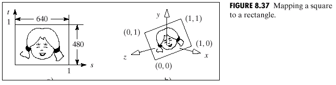
The following to commands tell OpenGL how to map a flat image to a 3D face. These two calls represent a pair of coordinates.
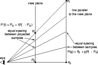
When the image is mapped to the 3D surface, and points on the image are sampled to map over to the surface, it can happen that aliasing starts to occurr. This can be reduced by interpolating.
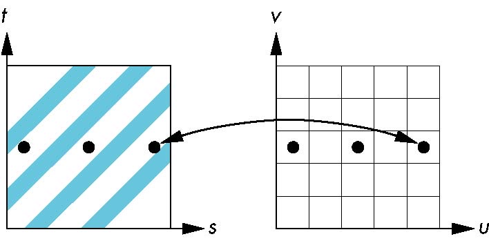
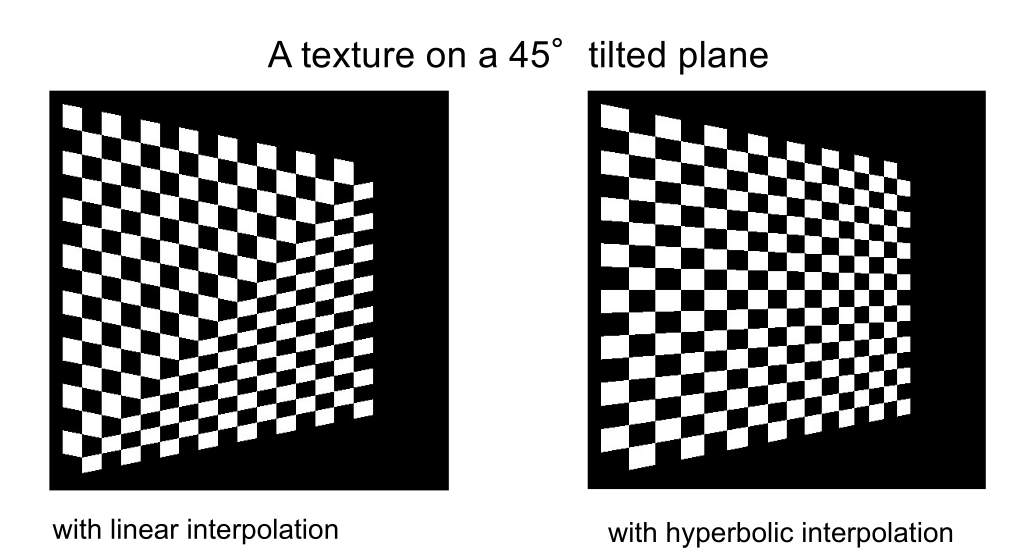
A second problem starts occurring when mapping a texture to a tilted plane and linear interpolation is used. Therefor, linear interpolation is not used for the interpolation of textures.
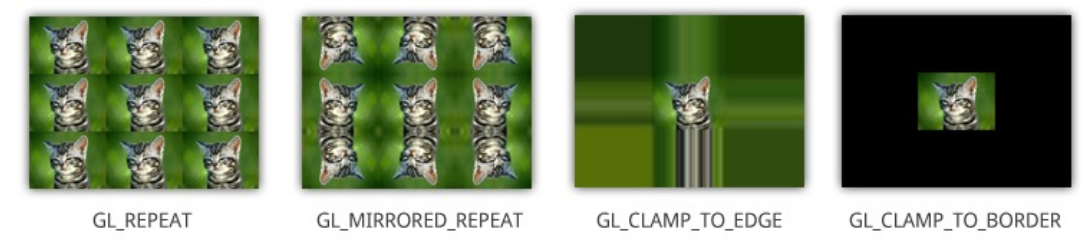
Wrap Mode
gl.texParameteri(gl.TEXTURE_2D, gl.TEXTURE_WRAP_S, gl.CLAMP)
gl.texParameteri(gl.TEXTURE_2D, gl.TEXTURE_WRAP_T, gl.REPEAT)
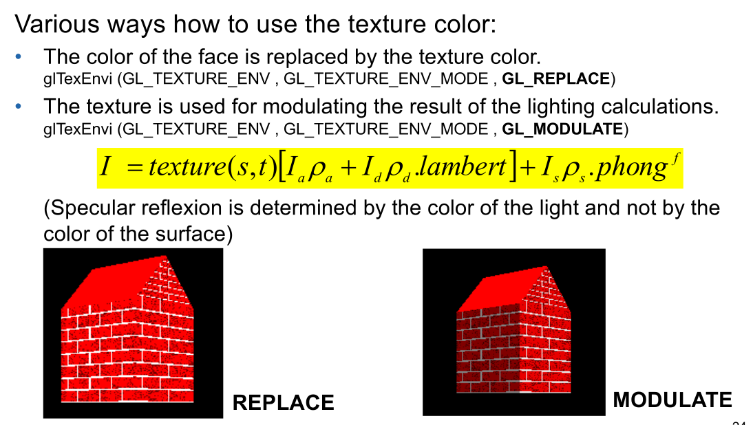
Light
Texture Filter
(texel = texture pixel)
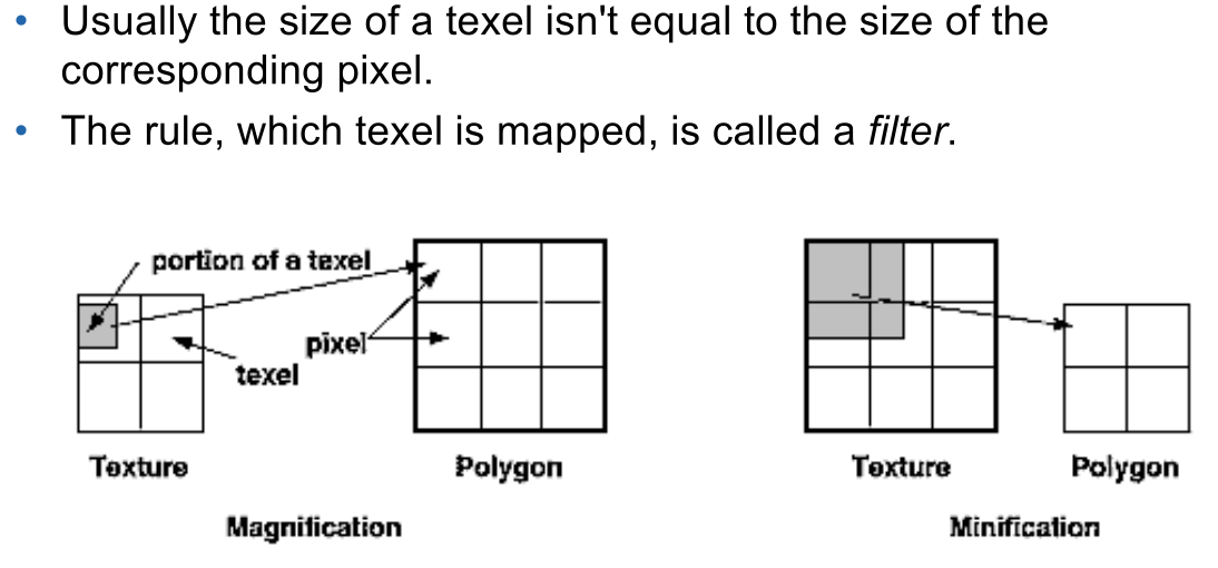
There are two situations: The pixel maps to an area less than one texel (the texel is smaller than the pixel and is enlarged), in which case magnification is used.
Secondly, the pixel can map to an area larger than the texel (the texel is bigger than the pixel and is shrunk), in which case minification is used.
There are two kind of filters used for both magnification and minification:
- nearest: The texel with the coordinates nearest to the centre of the pixel is used. However, this can result in aliasing artefacts
- linear: a weighted linear average of an area of 2x2 texels around the centre of the pixel is used.
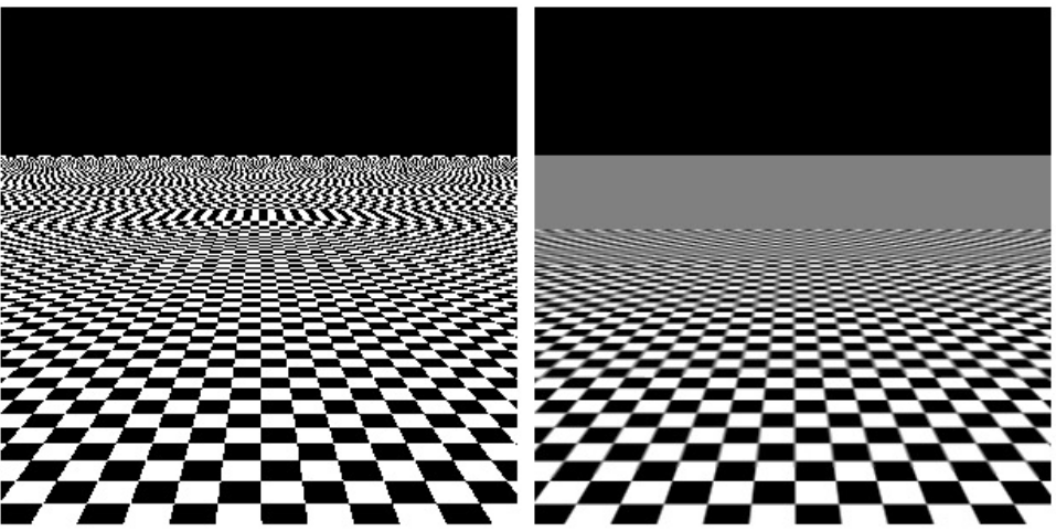
When choosing the wrong filter, it can lead to the following effects:
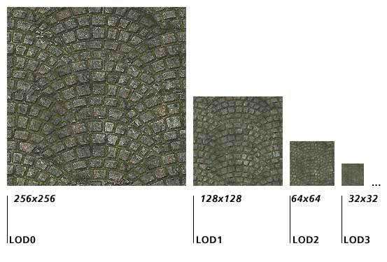
MIP Maps
MIP maps (multum in parvo / many things in a small place) are multiple textures of the same thing with the different resolution. The different level of details (LOD) are used depending how far the texture is away. This prevents the alaising from having too detailed textures, while also avoiding having muddy textures.
// loads a texture for a given mip map level
void glTexImage2D(GL_TEXTURE_2D, GLint level,
                  GLint components, GLsizei width, GLsizei height,
                  GLint border, GLenum format, GLenum type,
                  const GLvoid *pixels);

// builds the actual mip map
void gluBuild2DMipMaps();

// afterwards, OpenGL figures out which mipmap level should be used
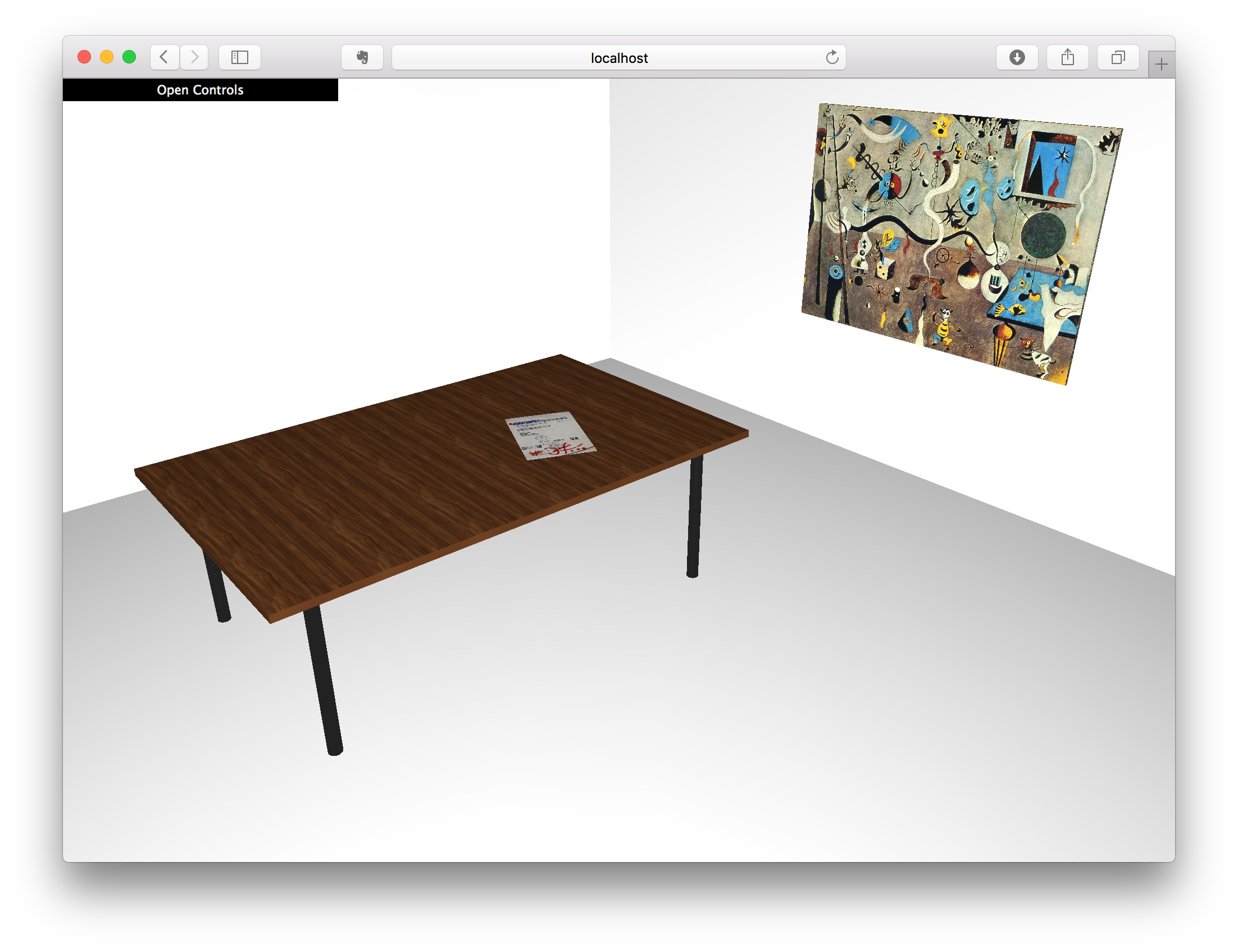
Textures in Three.js
var texture2 = THREE.ImageUtils.loadTexture("assets/wood.jpg");
texture2.wrapS = texture2.wrapT = THREE.RepeatWrapping;
texture2.repeat.set(6, 4);
var woodMat = new THREE.MeshPhongMaterial( { color: 0xffffff, map: texture2 } );
var box4 = new THREE.Mesh(new THREE.BoxGeometry(1, 1, 1), woodMat);
// mipmap is true by default
texture2.generateMipmaps = true;
UV Mapping
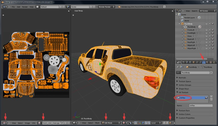
\(U\) and \(V\) denotes the axes of the 2D texture, while \(X\), \(Y\) and \(Z\) denote the axes of the 3D object in the model space. A UV map maps an image to a 3D object.
Environment Mapping
This is the process of rendering the environment of an object onto itself. This will make the object shiny. An environment is a texture, which has been built before-hand. There are two kinds: Cube Maps and Sphere Maps
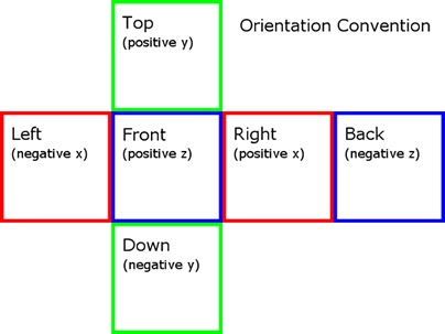
Cube Map
The cube map is rendered as a cube around the object. Than rays from the centre of the objects are shot and the colour of the first object they hit is the colour that pixel of the object becomes.
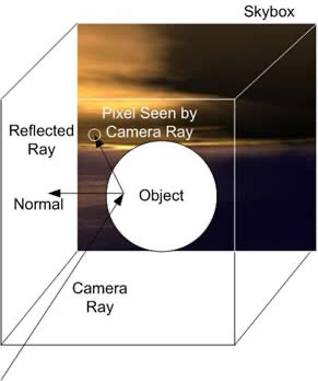
This represents a typical layout of a cube map:
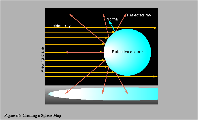
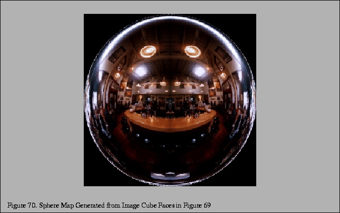
Sphere Map
A sphere map represents the reflection of an object from a specific view. However, a sphere map is simpler than an cube map, since it only consists of one texture. But this comes with the disadvantages of being view dependent and distorting.
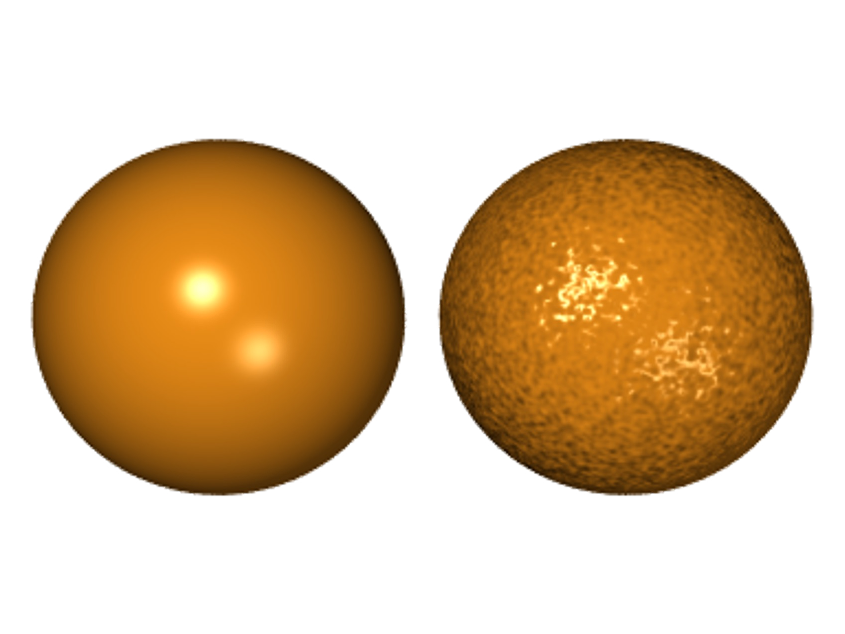
Bump Mapping
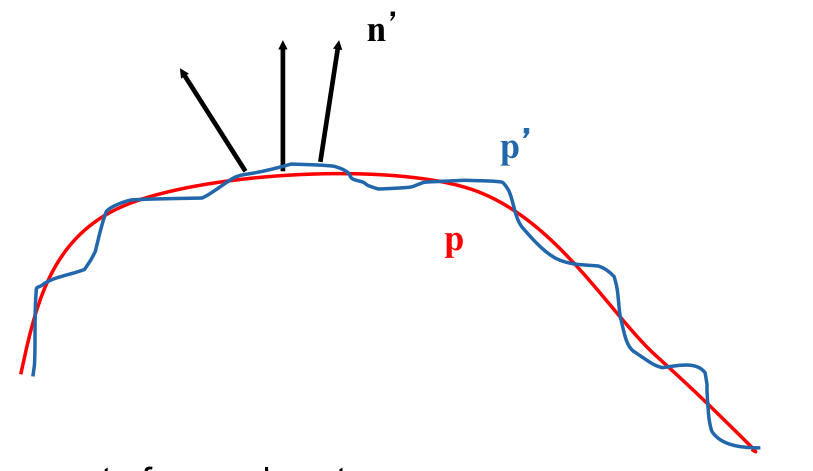
A bump map is a texture which modulates the surface normal (the normal vectors which are used for the shader calculation).
Instead of using the smooth line \(p\), the modified version \(p'\) is used. The
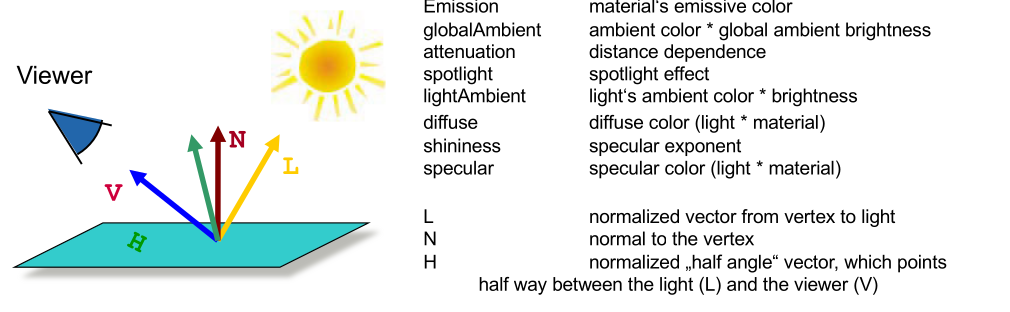
Vertex Color = emission + globalAmbient
    + sum(attenuation * spotlight *
          [lightAmbient +  max {L.N, 0} * diffuse) + (max {H.N, 0} ^ shininess)*specular])
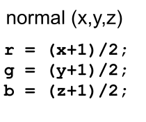
The following is a bump map:
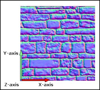
The z-axis modulation is defined by blue-channel, the y-axis by the green channel and the x-axis by the red channel.
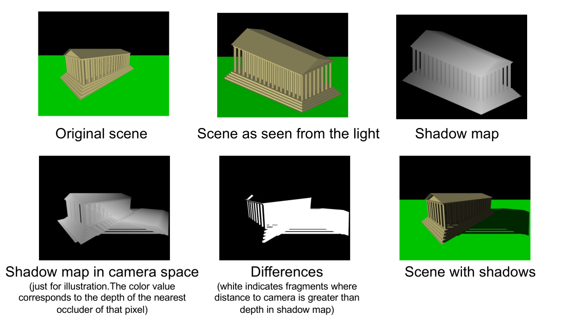
Shadow Map
A shadow map is being rendered as a second pass from the view from each light source. As such, a scene with lights is rendered in multiple passes. First from the view of all the lights, then from the regular view.
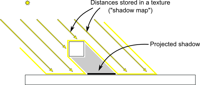
The idea behind rendering lights using a shadow map is that, for each light the scene rendered from its view. The resulting depth map will contain the distance to the nearest object from the light. From the depth map, the shadow map is created. When rendering from the camera's point of view, the distance of the light source of every fragment is calculated. If the distance is greater than the value in the shadow map, there is an object between the fragment and the respective light, and thus, the fragment is in shadow. Otherwise, the fragment is lit.
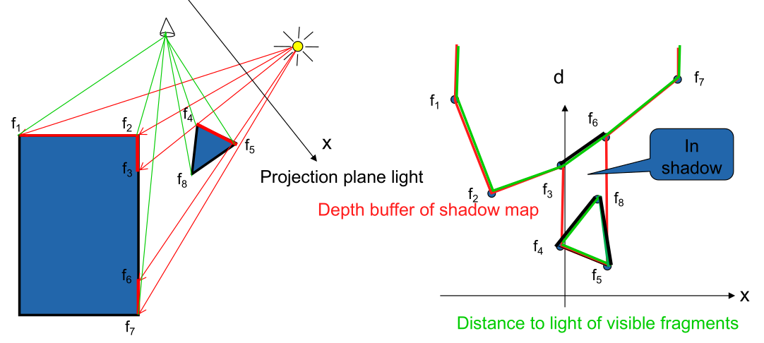
The following graphics shows the complete process:
Raytracing
Local illumination model
Light reflected by a surface (and therefore its colour) is dependent only on the surface itself and the direct light sources
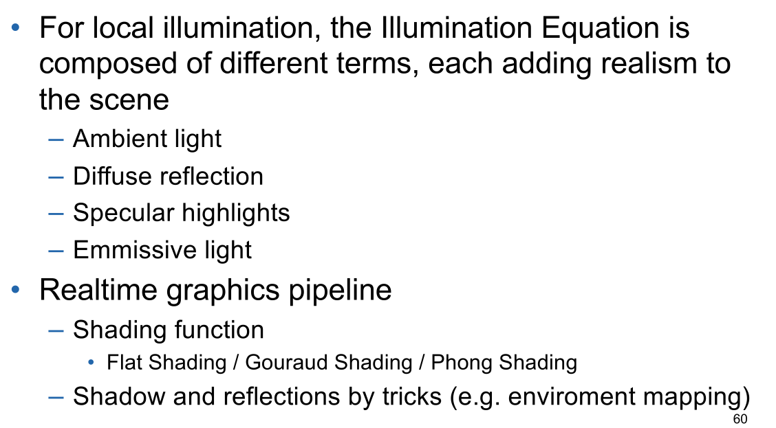
Global illumination model
Light reflected by a surface is dependent on the surface itself, the direct light sources, and light which is reflected by the other surfaces on the environment towards the current surface
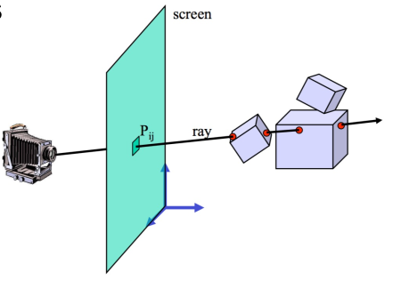
In this model, the camera shoots a ray for each pixel into the scene. The color of the pixel is determined by whatever the pixel hits.
To add shadows to this model, when hitting a surface, a ray is shot to the light source. If the rays hits anything in between, that point on the surface is in a shadow. These rays are called secondary rays.
The same trick can be used to add reflection. When hitting an object, secondary rays are shot into the environment, calculating the contribution to the colour of the pixel. If done recursively, a very realistic image can be generated. However, it is also compute intensive.
To stop the recursion, a stop criteria is used:
- Rays do not hit any objects
- Maximal tree depth is reached
- Ray contribution is neglibible
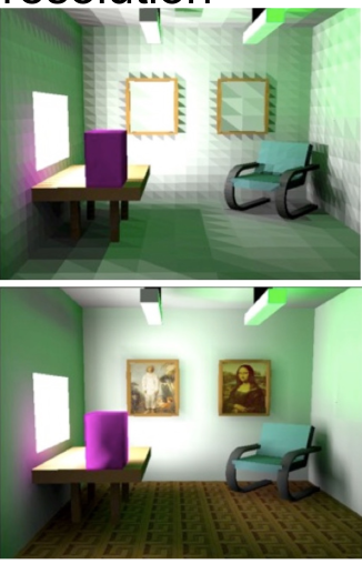
Radiosity
While ray-tracing renders reflections and refractions well, it misses colour bleed. However, this can be added by calculating the radiosity emitted by light hitting surfaces. Radiosity consists of two components:
- Energy emitted by the surface itself (for example a light source)
- Energy reflected from other surfaces
Radiosity is calculated by applying a finite element methods.
Since calculating the radiosity is very expensive, it's usually calcualted in a lower resolution. This is then interpolated.
Physical Based Rendering (PBR)
PBR emulates the interaction between light and materials. It differs from traditional rendering models, as it doesn't have to resort to tricks to create a realistic looking image.
A material has to following properties:
- Albedo The color of an object's diffuse light
- Metalness How strong light reflects
- Roughness