Assembler
Arm is little endian, meaning that the MSB comes first, the LSB comes last.
Basic Structure
                ; code area
                AREA    MyCode, CODE, READONLY

                ENTRY
start           MOVS    R4, #12
                ADDS    R3, R4, #5
                B start

                ; data area (writable)
                AREA    MyData, DATA, READWRITE
var_byte        DCB     0x0A, 0x12, 0xFF
var_halfword    DCW     0x1234, 0xEEFF
var_word        DCD     0x88776655
space1          SPACE   256 ; allocates 256 bytes
space2          %       256 ; same as above

                ; stack
                AREA    STACK, NOINIT, READWRITE
stack_mem       SPACE   0x00000400 ; 0x0000'0400
Data Types
There are bytes (DCB = 1 byte), halfwords (DCW = 2 bytes) and words (DCD = 4 bytes). They are layed out with LSB in the lowest address (little endian)
For example, 0x1A2B'3C4D is stored as 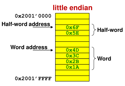
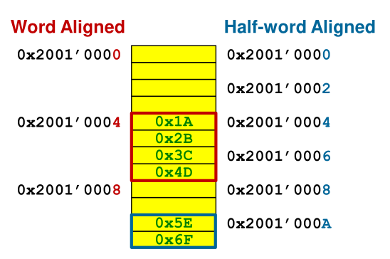
Another restriction is that halfwords addresses have to be divisable by 2 (address ends in even number), and word-addresses by 4 (address ends in 0, 4, 8 or C)
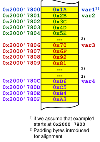
        AREA    example1, DATA, READWRITE
var1    DCB     0x1A
var2    DCB     0x2B, 0x3C, 0x4D, 0x5E
var3    DCW     0x6F70, 0x8192
var4    DCD     0xA3B4C5D6
The code above produces the following memory map:
Assembler Instructions
EQU
EQU creates a constant like #define does in C.
LDR
LDR can be used to load data from memory. There are multiple forms how LDR can be used:
LDR R5, mylitaThe value at the labelmylitais loaded. The instruction is translated toLDR R5, [PC, #...]where the offset cannot be too largeLDR R5, =0x2000This will allocate 4 bytes of space for0x2000in the literal pool and translate the instruction toLDR R5, [PC, #...]LDR R5, =CONST_ACONST_Ais defined by aEQUstatement and will be replaced while compiling resulting inLDR R5, =0x2000LDR R5, =mylitaThis will allocate 4 bytes of space for the address ofmylitain the literal pool and translate the instruction toLDR R5, [PC, #...]. The#...is stored in 8 bits and can address up to the address of4 x 255 = 1020LDR R5, [PC, #...]This will load a byte from the addressPC + #.... The intermediate needs to be word aligned.
The offset can be between 0 and 0x7C
There are also LDRSB for loading and extending signed bytes and LDRSH for loading and extending half words.
The same instruction (except for extending signed integers) also exists for storing data.
Airthmetic
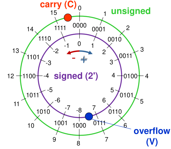
The carry bit has to meanings depending if adding or subtracting numbers:
- Adding: \(C=1\) means an overflow (with unsigned integers)
- Subtraction: \(C=0\) means an underflow (with unsigned integers)
When dealing with signed integers then the number only overflowed when \(V=1\).
Multi-Word Arithmetic
If 32bit integers are too small then the ADCS and SBCS instruction can help to do multi-word arithmetic.
The following will add R1R2R3 + R4R5R6:
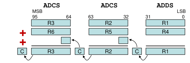
The ADCS Rdn, Rm instruction can be translated to \(Rdn=Rdn + Rm + C\)
The same is possible for subtractions:
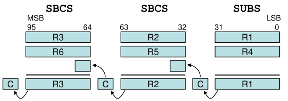
The SBCS Rdn, Rm can be translated to \(Rdn = Rdn - Rm - \mathrm {not}(C)=Rdn + \mathrm{not}(Rm) + C\)
Multiplication
Only unsigned integer multiplication is supported on the Cortex-M0.
Branches
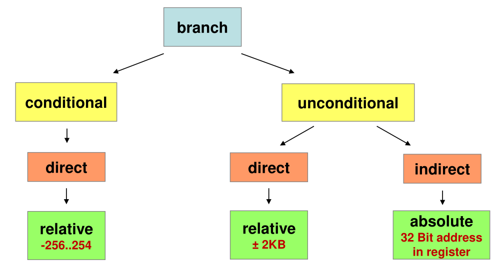
Structures
Ifs
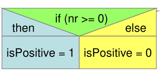
    ; if nr >= 0
    CMP R1, #0x00
    BLT else ; instead of >=, this inverts it to < but jumps to the else part

    ; if part
    MOVS R2,#1  ; isPositive = 1
    B end

else ; else part
    MOVS R2, #0 ; isPositive = 0
end
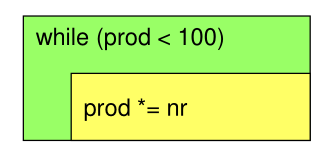
Do-While
    ; sum is in R2
    ; nr is in R1
    MOVS    R2, #0 ; init sum

loop ; do-while body
    ADDS    R2, R2, R1

    ; condition
    CMP     R2, #100
    BLT     loop
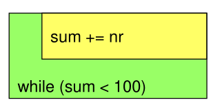
While
    ; prod is in R2
    ; nr is in R1
    MOVS    R2, #1

    ; jump to condition before executing the body
    B       cond

loop ; while-body
    MULS    R2, R1, R2

cond ; condition
    CMP     R2, #100
    BLT     loop
Jump Tables / Switch
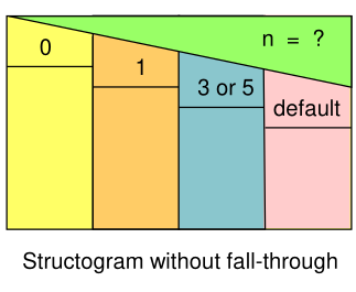
uint32_t result, n;
switch (n) {
case 0:
    result += 17;
    break;

case 1:
    result += 13;
    //fall through

case 3:
case 5:
    result += 37;
    break;

default:
    result = 0;
}
NR_CASES        EQU     6
case_switch     CMP     R1, #NR_CASES
                BHS     case_default    ; R1 >= 6 -> go to case_default
                LSLS    R1, #2          ; * 4
                LDR     R7, =jump_table
                LDR     R7, [R7, R1]
                BX      R7              ; go to label

case_0          ADDS    R2, R2, #17
                B       end_sw_case

case_1          ADDS    R2, R2, #13
                ; fall through

case_3_5        ADDS    R2, R2, #37
                B       end_sw_case

case_default    MOVS    R2, #0
end_sw_case


                AREA    myData, DATA, READWRITE
jump_table      DCD     case_0
                DCD     case_1
                DCD     case_default
                DCD     case_3_5
                DCD     case_default
                DCD     case_3_5
Interrupts
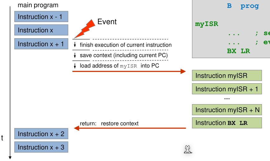
When code wants to react to some event on the system (like a button that's being pressed) then there are two ways to implement this. Either the code can constantly poll the state, checking over and over again if the event occurred. This, however, is inefficient and results in a lot of busy waiting, but it is simple, implicitly synchronised and deterministic.
Address Table
The following is a table of all important addresses for handling interrupts:
| Name | Address | Purpouse |
|---|---|---|
SETENA0 |
0xE000E100 |
Enable interrupt |
CLRENA0 |
0xE000E180 |
Disable interrupt |
CLRPEND0 |
0xE000E280 |
Clearing pending interrupt |
SETPEND0 |
0xE000E200 |
Triggering interrupt by software |
ACTIVE0 |
0xE000E300 |
Read-only memory to check if interrupt is active |
PL_IRQ0 |
0xE000E400 |
The 4 byte priority level of each interrupt (lower level = higher prio) |
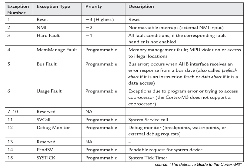
System Exceptions and Interrupts
Another solutions are interrupts: Arm processor differentiate between system exceptions and interrupts. System exceptions are errors created by events from the CPU (like a fault or the restart of the processor). Interrupts are created by events from peripherals or by a library.
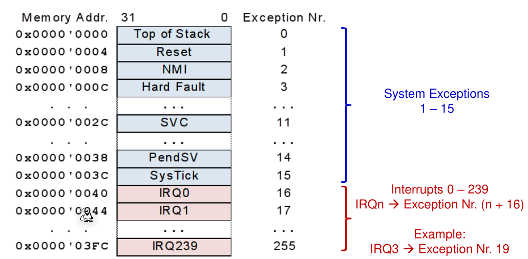
The following system exceptions exists. The interrupts from 0 until 239 are defined and are located after the SYSTICK system exception. (eg. IRQ14 has the exception number 30 at the address 120=0x78):
$$
IrqNr+16=ExceptionNr
$$
Interrupt Table
In the interrupt table is written where the processor has to jump if an interrupt or a system exception occurred. The interrupt table starts at the address 0x00, but there is no system exception 0. This is because at the address 0x00 the initial stack pointer is written. This results in when the CPU starts, it first initialise the stack with the initial stack pointer and then calls the reset handler which coincidentally is at the next address.
Example
main
            LDR     R0, =0xE000E100 ; address to enable the interrupt handling
            MOVS    R1, #1
            LSLS    R1, R1, #26     ; bit of IRQ26
            STR     R1, [R0]

ISR_Handler
            LDR     R0, =0xE000E280 ; address to clear pending interrupt
            MOVS    R1, #1
            LSLS    R1, R1, #26     ; bit of IRQ26
            STR     R1, [R0]
Execution of an Interrupt or System Exception
When an exception occurs then the CPU saves the register R0 - R3, PC, LR, R12, and xPSR. This allows the ISR function to be coded like a regular function.
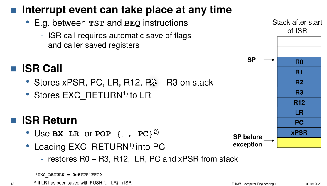
The cpu checks when calling BX LR if the magic value EXC_RETURN=0xFFFF'FFF9 is found in the LR register. If this is the case, then the previously saved registers are restored from the stack.
The following image shows a interrupt vector table.
The startup_ctboard.s initialises this interrupt vector table and sets default handler (marked with [WEAK] to tell the linker only use the default handler if no other definition exists).
Example:
; Vector Table Mapped to Address 0 at Reset
AREA RESET, DATA, READONLY
__Vectors   DCD __initial_sp        ; Top of Stack
            DCD Reset_Handler       ; Reset Handler
            DCD NMI_Handler         ; NMI Handler
            DCD HardFault_Handler   ; Hard Fault Handler
            ...
            ....
            ; Interrupts
            DCD IRQ0_Handler        ; ISR for IRQ0
            DCD IRQ1_Handler        ; ISR for IRQ1
            DCD ...
The following is a diagram showing the states of the interrupt handler.
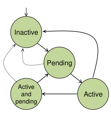
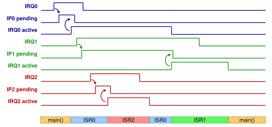
- Inactive: Exception is not active and not pending
- Pending: Exception occurred and is waiting to be handled by the CPU
- Active: Exception is being handled and has not finished yet
- Active and Pending: An exception is being handled by the CPU and another exception occurred and is waiting to be handled.
To model all possible states, two bits are necessary, one for if an interrupt is pending and one if the interrupt is active.
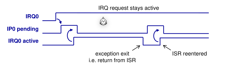
The following diagram shows the two bits and an interrupt request bit.
When the IRQn goes to high and interrupt occured then the Interrupt Controller sets IPn to high. As soon as the CPU has finished the context switch, IAn will be set to hight by the CPU and the interrupt controller will set IPn to high. The IRQn needs to be reset by the interrupt handler.
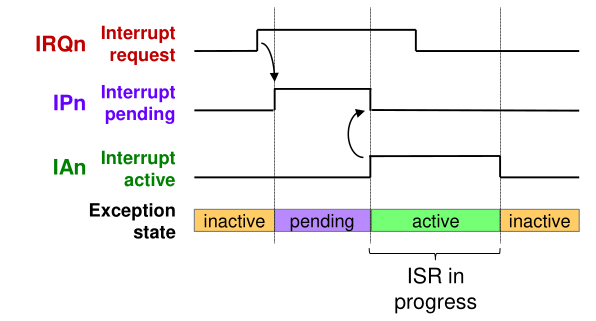
If the interrupt handler doesn't reset the IRQn then the interrupt controller will think that another interrupt is pending and the CPU is caught in an infinite loop.
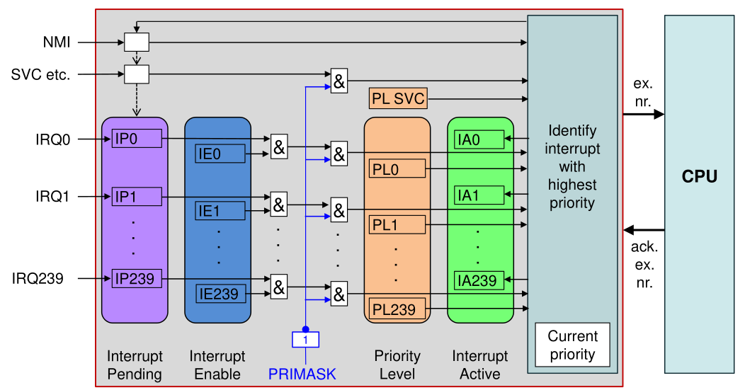
Activate and Deactivate all Interrupts
PRIMASK is a Bit, which when set to 0 , all interrupts are disabled. The bit can be set with CPSID i and unset CPSIEi.
Activate and Deactivate specific Interrupts
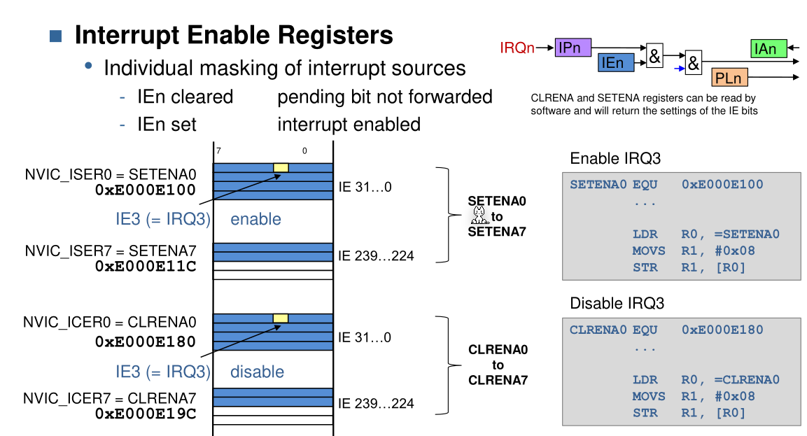
; enables IRQ16
MOVS    R1, #1
LSLS    R1, R1, #28         ; enables IRQ28
LDR     R0, =0xE000E100     ; loads memory to enable interrupts
STR     R1, [R0]            ;

; disables IRQ16
MOVS    R1, #1
LSLS    R1, R1, #16         ; enables IRQ28
LDR     R0, =0xE000E180     ; loads memory to disable interrupts
STR     R1, [R0]            ;
Control Interrupts
By writing to the bit of the IRQ number, a interrupt can be created by software (0xE000E200), the pending request can be deleted (0xE000E280) or test if an interrupt is active ( 0xE000E300).
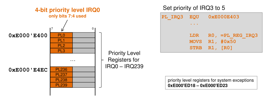
Priority Levels
Each exception has a priority level. A lower priority level translates to a higher priority (-1 has a higher priority than 10)
To set the priority a 4-bit value (on the Cortext-M0 a 2-bit value) can be written to an address between 0xE000'E400 and 0xE000'E4EC. Only interrupts can be prioritised manually, system exceptions already have predefined priorities.
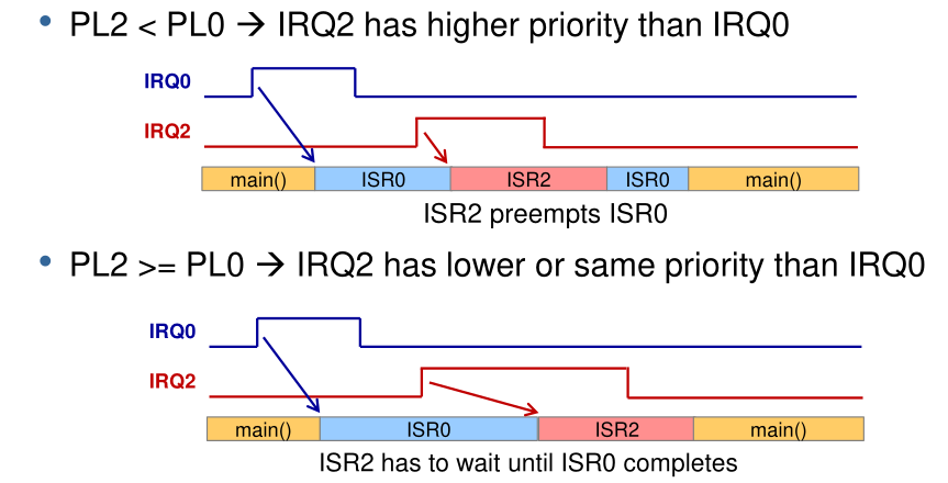
In the diagram above, a situation where either ISR0 or ISR2 has been prioritised. If ISR2 is prioritised then ISR0 is paused (but its active bit is still set) and ISR2 is run.
Below is a more complete diagram. It assumes the following priorities: RQ0 PL0 = 0x2, IRQ1 PL1 = 0x3 and IRQ2 PL2 = 0x1
Nested Vectored Interrupt Controller (NVIC)
The NVIC handles part of the complexity of calling interrupt handlers.
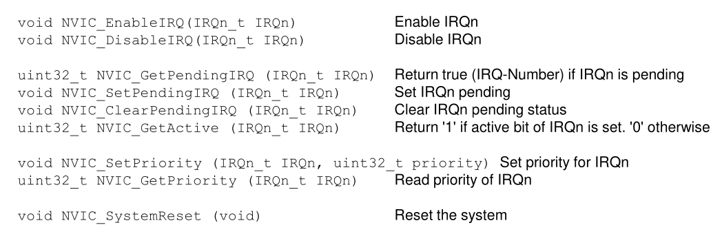
Interrupts in C
There is a library for C to allow the user to know have to use registers directly but rather just call functions.
Data Consistency
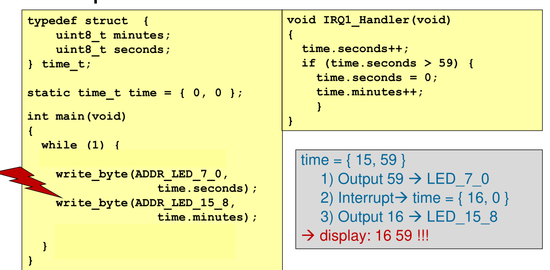
To fix this issue, the two write_byte(...) calls should be wrapped in __disable_irq() and __enable_irq().