Timer
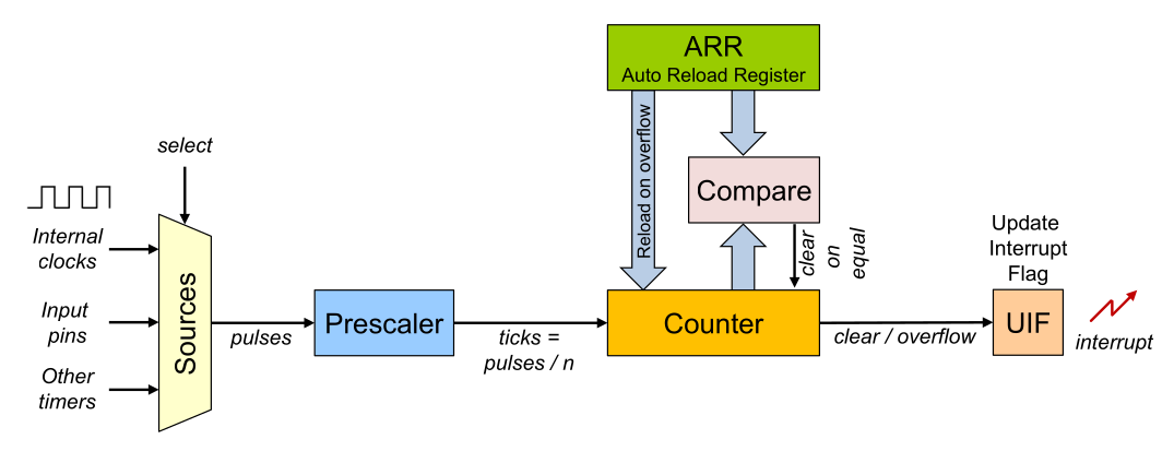
The counter counts up or down with every pulse it receives. If the counter hits 0, then the ARR is loaded in the counter, and if the counter hits ARR then 0 is loaded into the counter. The counter will reach the value of the ARR registry, meaning that the timer counts from 0 to ARR inclusively.
The pulses from the CPU might still be too fast. To further slow down the counter, a prescaler can be used.
In the following example, the prescaler is set to 4 and the timer is configured as a countdown timer with the ARR registry set to 2546:
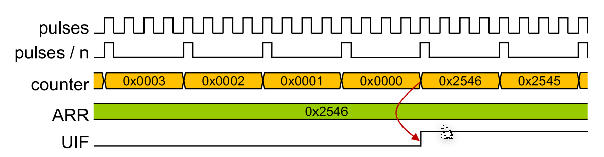
Importantly, the UIF flag has to be reset in the interrupt service routine. Otherwise, the CPU will invoke the interrupt immediately afterwards.

The frequency can be calculated with: $$ f_{end}=\frac{f_{initial}}{PreScaler \cdot (f_{ARR})}\ f_{ARR}=\frac 1 {ARR + 1}\ $$
STM32F4xx
The TIM2 and TIM5 are 32-bit timers and the TIM3 and TIM4 are 16-bit timers. Both timer types can count up or down and can have a prescaler between 0 and 65536.
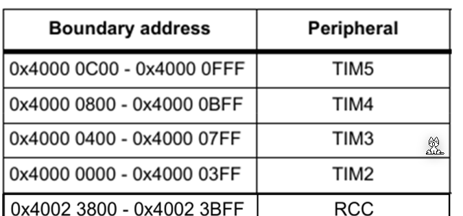
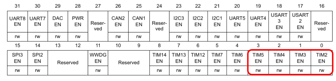
To enable the timers, the respective control bits need to be enabled in the reset and clock control (RCC) registry.
The following shows the RCC registry configuration:
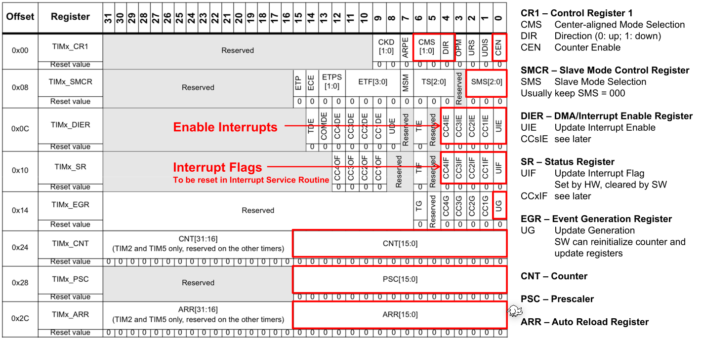
DIR: Tells the timer if it should count up (0) or down (1)UIE: Enables the interrupt from the timerCMS(Center-alligned mode): should be set to00to use theDIR
In C, the structures TIMx can be used to configure it (e.g. TIM2->ARR = 3200 - 1;).
The TIMx_ARR (TMx->ARR) is the ARR flag, the TIMx_CNT (TIMx->CNT) is the counter variable and the TIMx_PSC (TIMx->PSC) is the prescaler.
When the center-aligned mode is enabled, the timer counts from 0 up to ARR-1, and then from ARR to 1. This leads to the counter register having the following values: [0, 1, 2, 3, 4, 3, 2, 1, ...] for ARR=4.
The slave mode control register (SMCR) is usually set to 000 which causes the timer to use the internal clock as the clock source.
Input Capture
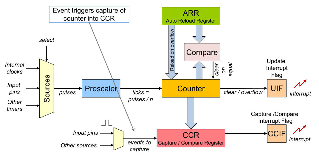
After the CCR captured a value it needs to be re-enabled before the next value is written into the CCR register.
In the capture mode, when the input triggers (can be configured) then the counter is stored to the CCR register and an interrupt is generated.
In the compare mode, when then CCR is equal to the counter then an interrupt is generated.
Pulse Width Modulation (PWM)
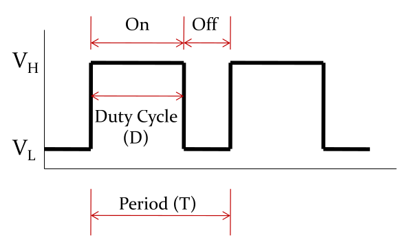 $$
V_{avg}=D\cdot V_H + (1-D)\cdot V_L\
DutyCycle=\frac{On Time}{Period}\cdot 100\%
$$
$$
V_{avg}=D\cdot V_H + (1-D)\cdot V_L\
DutyCycle=\frac{On Time}{Period}\cdot 100\%
$$
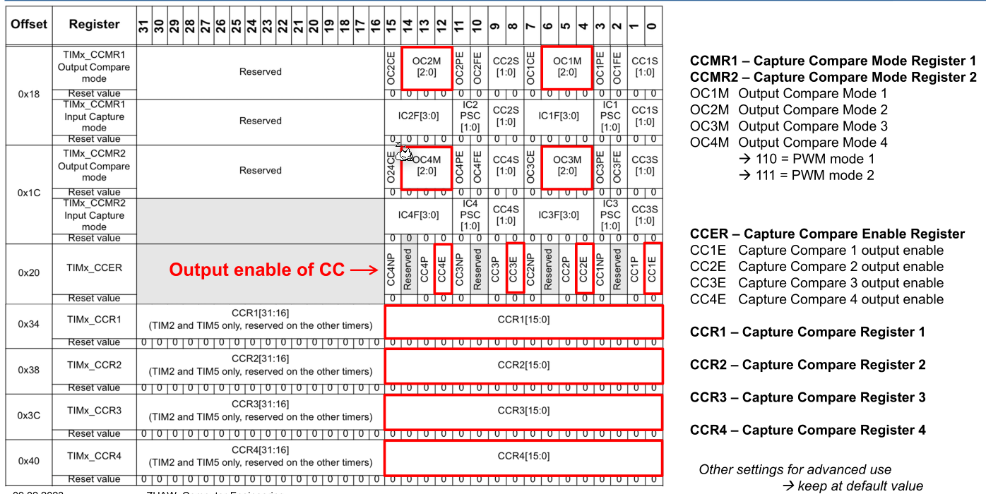
PWM signals can be generated by the timer hardware by setting the CCR register to the \(1-DutyCycle\) or \(DutyCacle\) (depending on the PWM mode). The compare output from the CCR (if the counter value is higher then the CCR register) is directly used as the PWM signal.

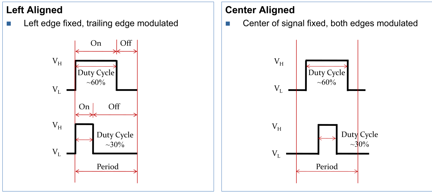
Depending on the PWM mode and if the counter counts up or down, CCR needs to be set to \(DutyCycle\) or \(1-DutyCycle\).
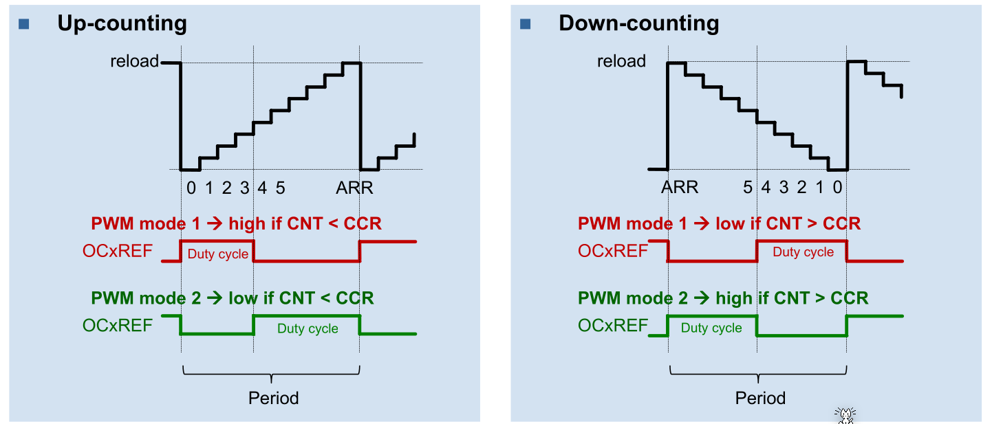
To calculate the CRR for a duty cycle:
- When up counting: then \((ARR + 1)\cdot DutyCycle\)
- When down counting: then \((ARR + 1)\cdot DutyCycle-1\)
TODO: Calculate ARR and CCR from specifiction $$
$$